DT1000 / MA6100 Digitalker Evaluation Board
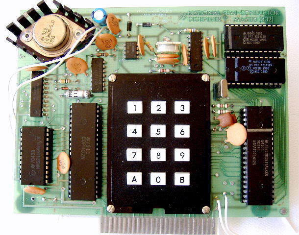
Image gallery
A complete talking workbench
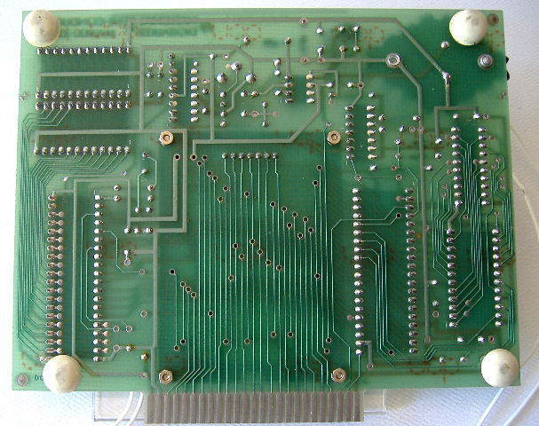
Available by early 1981, the DT1000 was an evaluation board for engineers considering Digitalker speech in their own products. Unlike a bare chip kit, it arrived with the circuitry and control software needed to demonstrate a working voice. A regulated 7–11 V DC supply and a suitable loudspeaker were the remaining requirements. Its onboard amplifier delivered approximately half a watt.
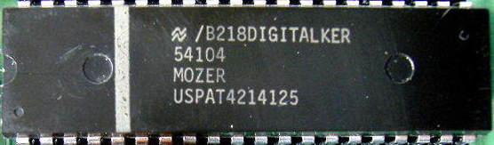
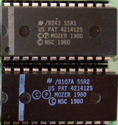
The photographs show the Digitalker 54104 speech processor and SSR1/SSR2 vocabulary ROMs. National’s instructions identify a COP402 COPS microcontroller as the board’s controller. It scanned the twelve-key keypad and ran the demonstration modes; the speech processor reconstructed the voice from data in the two separate ROMs. The DT1050 was a related processor-and-ROM kit, rather than this complete evaluation board.
Words selected by number
On power-up the board announced “This is Digitalker.” Entering a three-digit vocabulary address and pressing A selected an utterance; A repeated that selection, while B stepped through successive entries. The board retained only the last three entered digits, making an incorrect entry easy to replace.
The manual defines 144 valid selection addresses, numbered 000–143. These cover spoken material, tones, and five silence durations. Its introductory description advertises 138 words, but the address table is the useful programming reference: an addressable entry is not necessarily an individual word. The vocabulary includes numbers, alphabet letters, and terms suited to measurements, prompts, and equipment status.
This was stored-vocabulary speech, rather than a text-to-speech engine. A host could select and combine the supplied entries, but typing an arbitrary sentence could not create words that were absent from the ROMs.
Phrases, a talking clock, and a game
The board could store three user-assembled phrases in RAM. Mode 400 held twelve selection addresses; modes 500 and 600 held six each. During construction, the first press of B previewed an entry and the second stored its address. The three phrase slots could be played in different orders, allowing a sequence of up to 24 stored addresses. These were temporary phrase selections, not new recordings burned into the vocabulary ROMs.
Silence entries were an important part of phrase construction. National recommended experimenting with pauses to make joined words sound more natural, including short gaps around certain consonants. The vocabulary also supplied an “SS” sound for forming plurals and prefixes such as “centi,” “milli,” and “re.” These offered some flexibility without making the vocabulary unlimited.
Mode 700 demonstrated a talking-clock message with an editable middle: “The time is … P.M.” It illustrated how fixed speech could surround a changing value in a clock or instrument. Mode 800 ran a reaction-time game: the board spoke ten random digits, waited for the corresponding keypresses, and then announced the accumulated response time. Random pauses between prompts were excluded from that time.
Other modes repeated a single entry automatically, cycled through the vocabulary, and spoke the hexadecimal equivalent of an entered decimal address. The evaluation board therefore demonstrated both the voice itself and several practical ways to control it.
Connecting an external computer
The edge connector exposed the speech processor’s eight-bit selection bus and control signals. National explicitly required removing the COP402 before using an external processor to control the Digitalker portion of the board. The host could then select ROM entries directly while retaining the board’s speech circuitry, filter, and amplifier.
A low chip-select signal enabled a command. The rising edge of the write strobe latched the selection and executed the command chosen by CMS: start speech and reset the interrupt, or reset the interrupt alone. INTR went high when the speech sequence finished. Starting another sequence before completion immediately replaced the current one, so software needed to watch completion when assembling uninterrupted phrases.
The manufacturer’s connector drawings and electrical tables remain essential for wiring a surviving board. The supply must be regulated; TTL-compatible control signals and the board’s 7–11 V power input are separate electrical considerations.
How Digitalker produced its voice
Digitalker reconstructed compressed speech waveforms from an external ROM, preserving characteristics of the recorded voice. This differs from building an arbitrary word from a general phoneme inventory. It also explains why changing the vocabulary meant changing the encoded speech data, rather than merely changing a list of written words.
The Mozer and Stauduhar patent identified on the processor describes compression using delta-modulated waveform information, repeated pitch periods, and waveform symmetry. Reusing sound segments reduced the storage needed for recognizable speech. The speech processor interpreted its ROM data and produced an analog signal that passed through the board’s filter and audio amplifier.
The separate speech ROMs made the processor reusable across different vocabularies. Producing a custom ROM required speech prepared and encoded for the Digitalker system; an ordinary audio recording could not simply be copied into an EPROM. The standard SSR1/SSR2 pair made this board immediately useful for evaluating familiar English words and technical prompts.
National also emphasized the loudspeaker and its enclosure. The evaluation board could drive a speaker, but a tiny or unbaffled speaker would not reveal the voice’s full quality. Demonstrating speech synthesis involved the complete audio path, not just the chip.
Hear the Voice Messenger
Digitalker — numbers and alphabet
Digitalker chipset demonstration.
Specifications
- Manufacturer
- National Semiconductor
- Model / board marking
- DT1000 / MA6100
- Speech processor
- Digitalker MM54104
- Vocabulary ROMs
- SSR1 and SSR2
- Onboard controller
- COP402 COPS microcontroller, identified in the manufacturer’s instructions
- Selections
- 144 valid addresses, 000–143
- Phrase storage
- Three RAM slots: 12, 6, and 6 addresses
- Power
- Regulated 7–11 V DC
- Audio amplifier
- Approximately 0.5 W
- Controls
- Twelve-key keypad and external processor interface
Keypad demonstration modes
| Code | Function |
|---|---|
| 200 | Automatic repeat or vocabulary cycle |
| 300 | Decimal-to-hexadecimal address conversion |
| 400 | Phrase slot: twelve addresses |
| 500 | Phrase slot: six addresses |
| 600 | Phrase slot: six addresses |
| 700 | Talking-clock phrase with editable insertion |
| 800 | Spoken reaction-time game |
| 900 | Return to power-up/manual control |
Documentation and downloads
- National Semiconductor Digitalker documentation
Includes DT1000 instructions, keypad modes, external processor connections, and vocabulary reference.
- DT1050 Digitalker chip-kit datasheet
Companion technical reference for the speech processor and standard vocabulary ROMs.